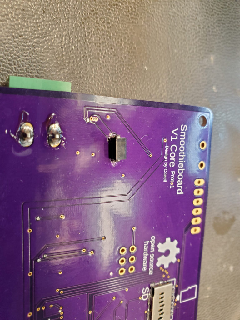
Over the last few months I have been making some prototypes for boards which I felt may be useful to the community. One of which being this board.
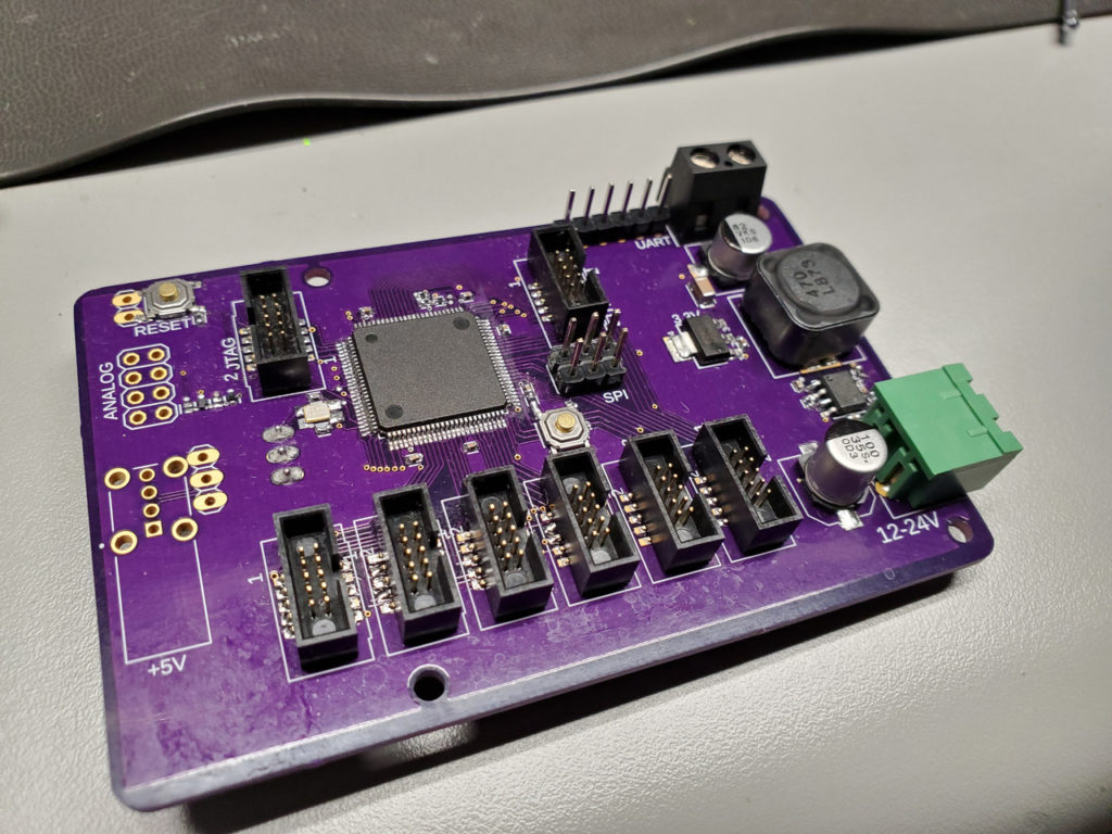
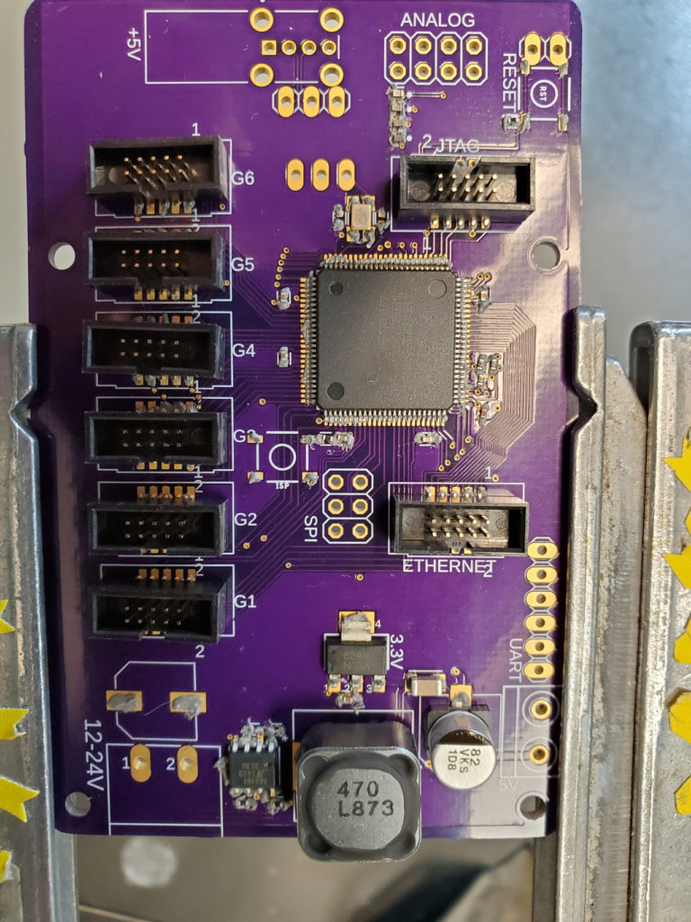
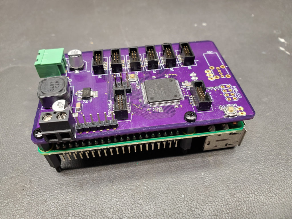
It is a Smoothieware V1 compatible board which is setup in the same way as the planned “V2 Core”. This setup eliminates all the output devices (ethernet, fets, stepper drivers, etc) and just has the basics which the MCU needs to function.
Every other pin on the board is brought out to the gadgeteer headers in order to use the modular expansion boards which are a big part of the V2 design. More info here: http://goo.gl/XP5iZc https://smoothieware.org/blog_15
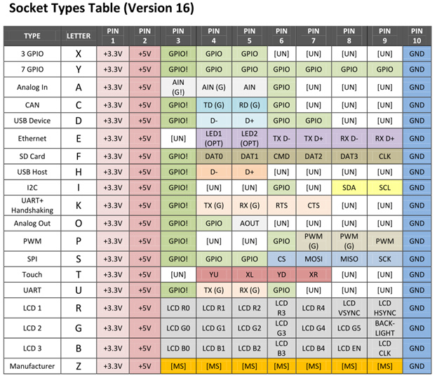
These headers have a standardized pinout (7 GPIO, 5v, 3.3v, GND) which will allow users to plug/config add on boards which can easily be added or removed from a machine. This setup we hope will allow not only more expansion capabilities but will also allow users to update/upgrade their “output devices” as they evolve. No longer will otherwise happy users be limited by new stepper drivers or output modules. Boards can be designed easier and cheaper as you can select board weight and routing to suit the specific nature of your module. Modules which have significant electrical noise can be easily isolated from the more noise sensitive areas of the electronics as well as allowing for ease of heatsinking and/or rail mounting.
As some of you may notice…the board does not have a USB header on it. How do you control it you may ask?
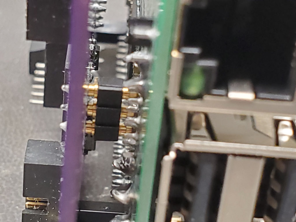
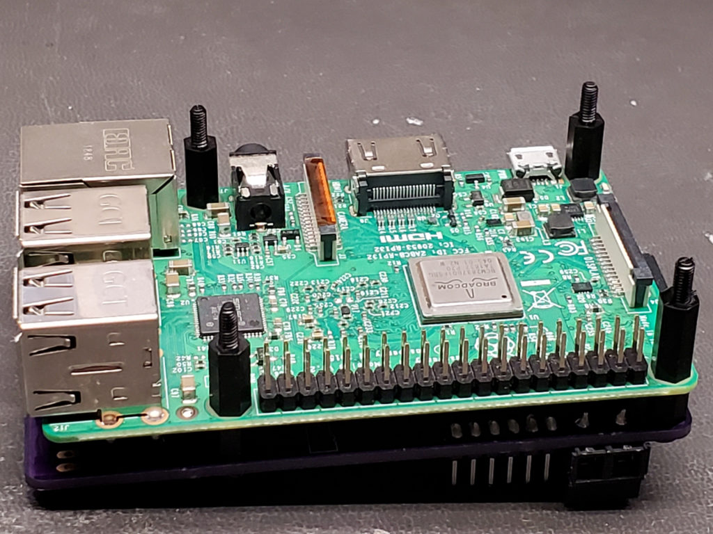
I designed this board to mount to the backside of a Raspberry Pi 3b. The mounting holes align and as you tighten them the spring connector on the bottom of the board makes contact with the test points on the bottom of the Raspberry pi which carry the USB D+/D- signals. This allows not only the ability to eliminate the USB connector and cable but also allows isolation of the 5v line from the Raspi (which is known for not being the best at sourcing current). In this design I also created a passthru USB which comes from the Raspi and passes through the V1 Core board but does not use the Raspi 5v. This addition allows you to run higher power devices (webcams, pendant, etc) without the need for an external powered USB hub.
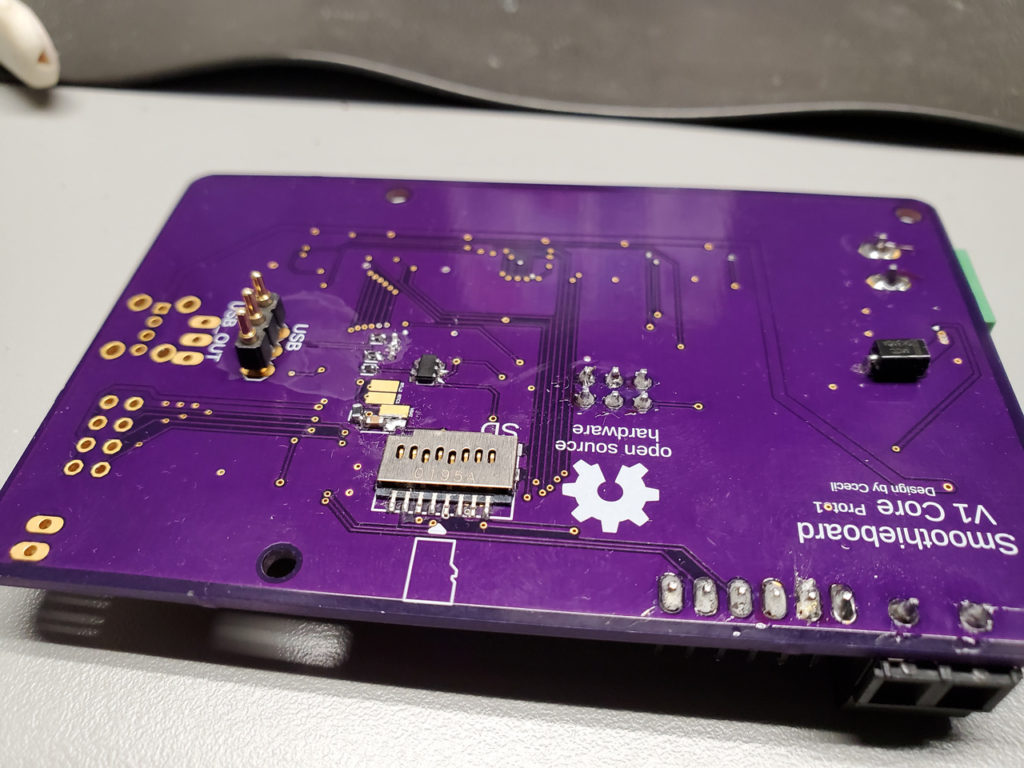
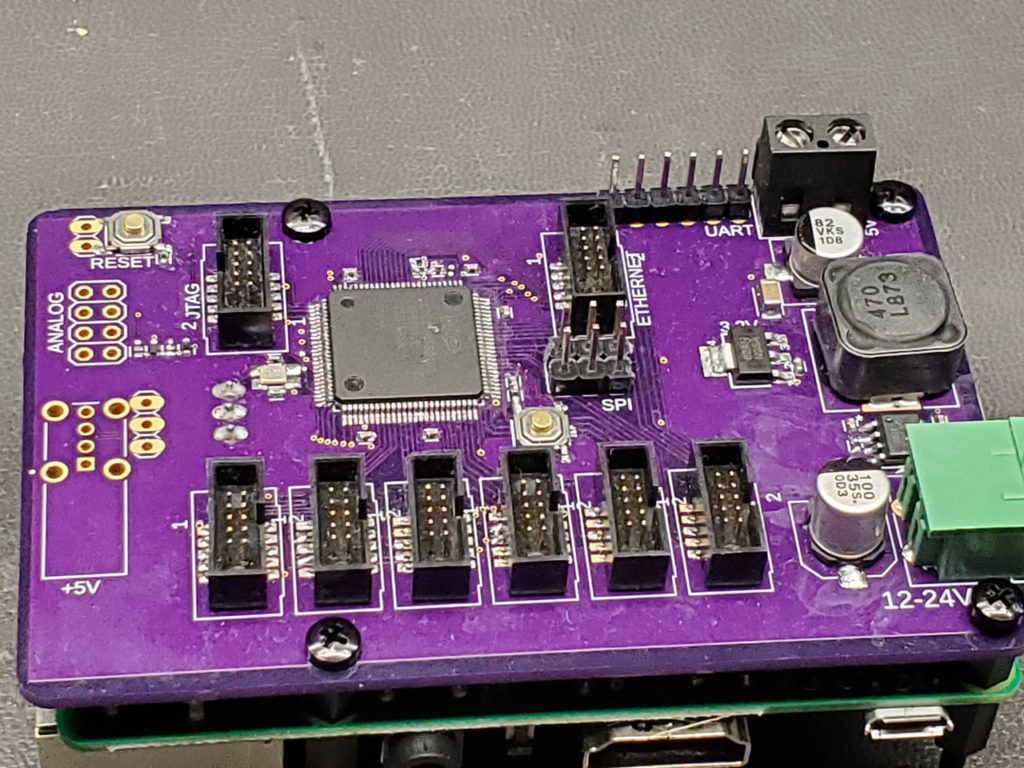
Onboard, the V1 core also has a 5v@3a voltage regulator. It will have enough power to run the board, Raspi and a Touchscreen for a setup such as Smoopi (https://github.com/wolfmanjm/kivy-smoothie-host).
It is a very compact form factor so it should not be an issue to build this into most existing setups and then wire any modules through a harness which can be shielded and isolated from other electrical noise.
Now…onto the bad news. Currently, we are in the middle of a shortage of LPC1769 chips so this board will likely not be produced any time soon…and likely it will be after the similarly designed V2 core is released. I will get the files up soon so anyone can have a PCB made and if they have the chips they can build one of these for themselves. There are a few errors I made which I need to fix first but anyone with access to Eagle or Fusion360 can view and modify the files.
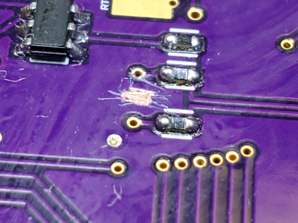
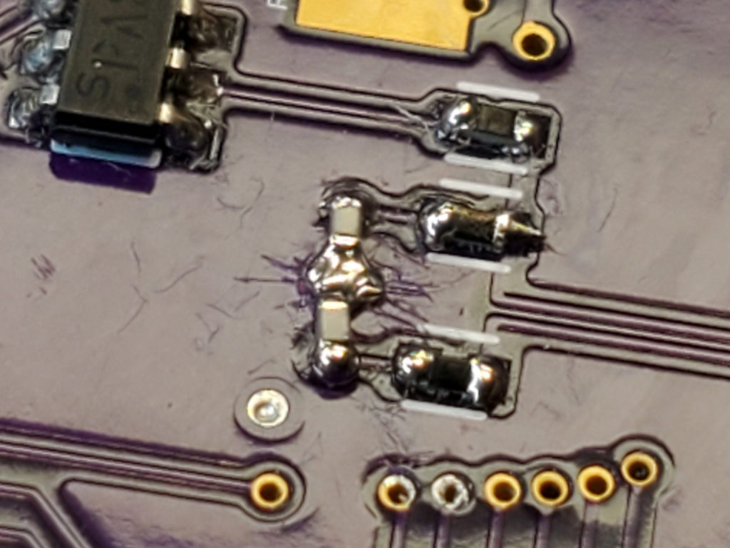
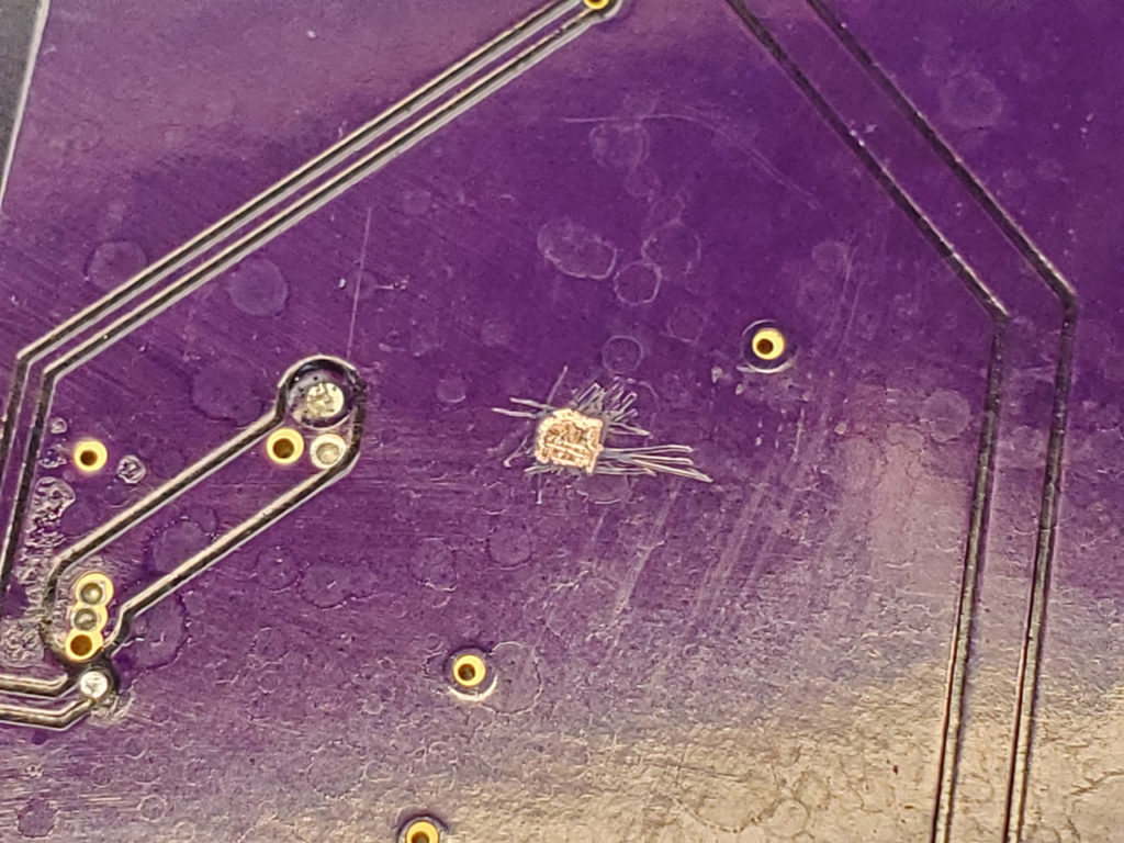
This design has not been fully tested yet and there are/were errors so it should be treated as the prototype it is. This board needs significant review and test before it is to be considered for a production environment. Do with it as you may.
Links to project files coming soon.