Slogging along through the assembly process. All was going well. PnP was cooperating with me. I produced 50pcs of the V2 2660 prime (bottom side) and had the oven all warmed up and ready to go.
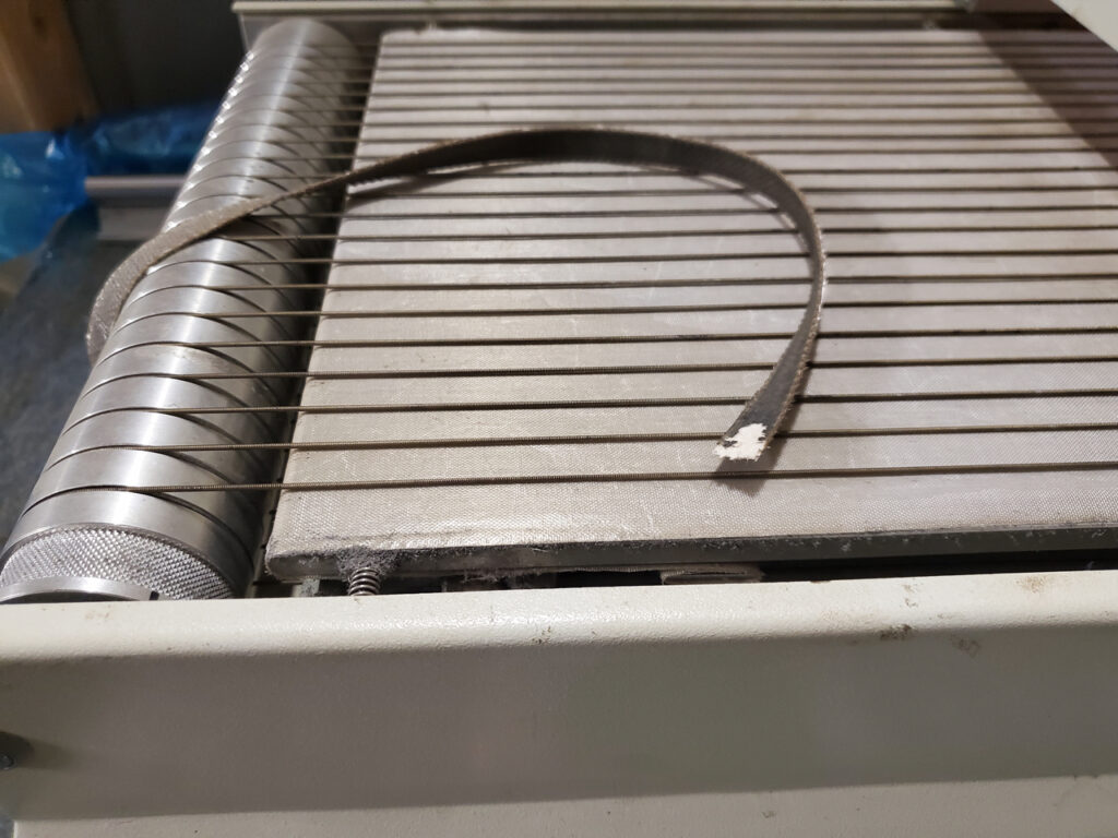
I started flowing some boards when a strange sound caught my attention. Next thing I notice the conveyor stops moving. Turns out the belt which drives the belt pulleys broke.
Of course, I was 6 boards in through a lot of 50 so this was quite inconvenient. I managed to spin the spindles by hand and was able to get the flow profile to at least be passable (these will reflow later when I do the tops so they should be alright).
So now what? This oven is my spare oven…the big oven requires 3-phase which the current temporary shop does not have. I suppose we could give up right?
Nah…we have come this far…and fortunately for me…I am me.
So I noticed the belt issue a while back when I was doing some other work on the machine. I knew it was a failure point which was going to happen someday soon. So my first thought was get a replacement…until I started looking around at what is involved in changing the belt. Basically, it requires tearing the entire machine down to the frame in order to get the belt into where it needs to go.
I am not going to get into the glaring design flaw here that clearly makes it nearly impossible for the end user to replace a wear item…but also the belt is driven by a single motor and routes through the tunnel…so it is exposed to heat and flux.
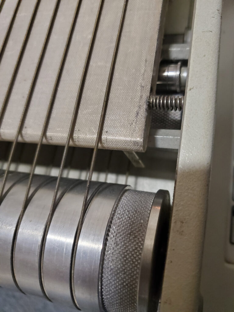
The conveyor is driven by 2 rollers. One on each end and stretched between these rollers are “continuous springs” which the boards sit on while they are moved through the oven. This requires both rollers to be driven equally or the spring will be stretching/compressing leading to premature wear and failure.
So my first thought was put in 2 motors, gearhead dc motors with encoders to match the speed would work. Drive it with an arduino or something and then the speed would match between the 2 motors consistently. This option is cheap enough..but I didn’t have the parts on hand for it.
Second thought was use some stepper motors (certainly have those on hand) and a smoothieboard to run the speeds. This be fairly easy…just set a config and run a continuous jog to set the speed constant.
Easy enough…parts are on hand…but this seemed excessive.
Jokingly, I said..”Why not a 555 timer?”
Then thought…wait..that actually will work.
“I bet someone has done this already”
Quick google search I ran across a HaD page which showed this exact thing…and being my lazy self that didn’t feel the need to rethink 555 timers too hard I looked over the circuit…said “Yeah…that’ll do” and started searching around the shop for some projects that still had some 555 timers in them.
I found 2 options…a brand new 556 (dual 555) in a Radio Shack baggie. Or a small intervalometer board that I built a decade back that I could salvage a 555 from. I chose the latter.
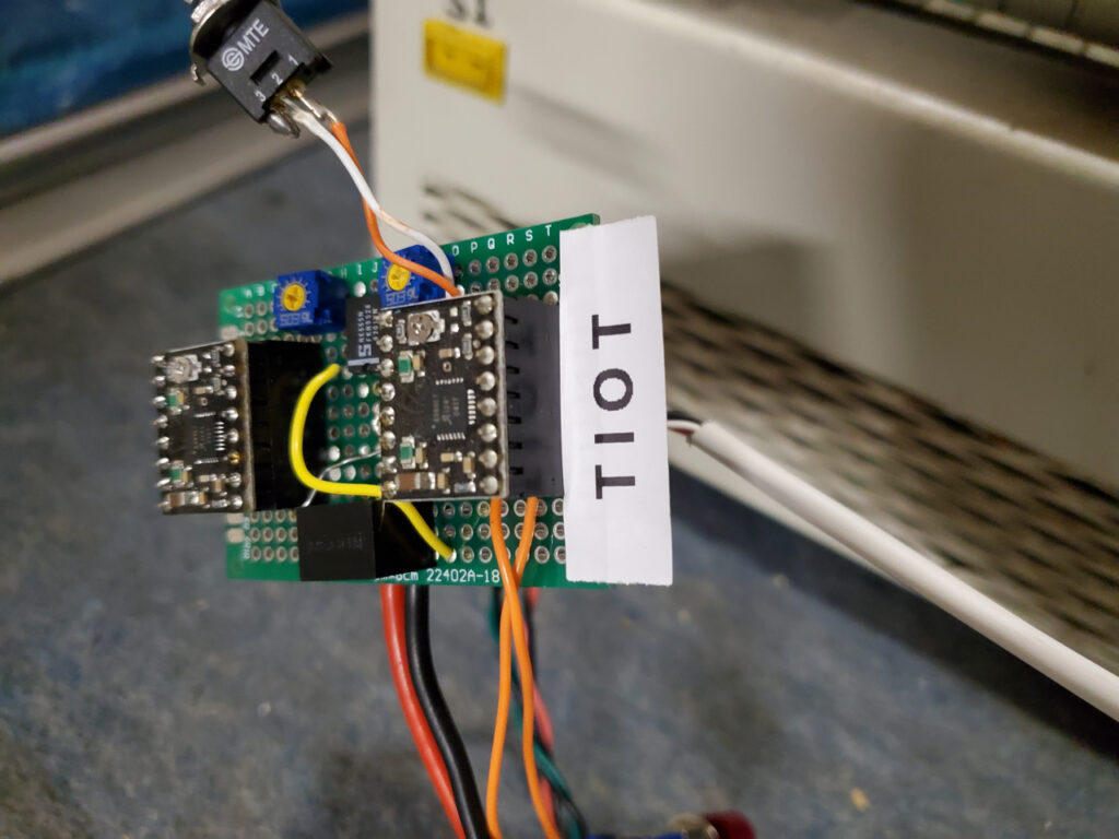
After doing a bit of redrawing of the circuit in kicad 7 and verification of the timing I moved on to building the circuit on stripboard (This is only temporary).
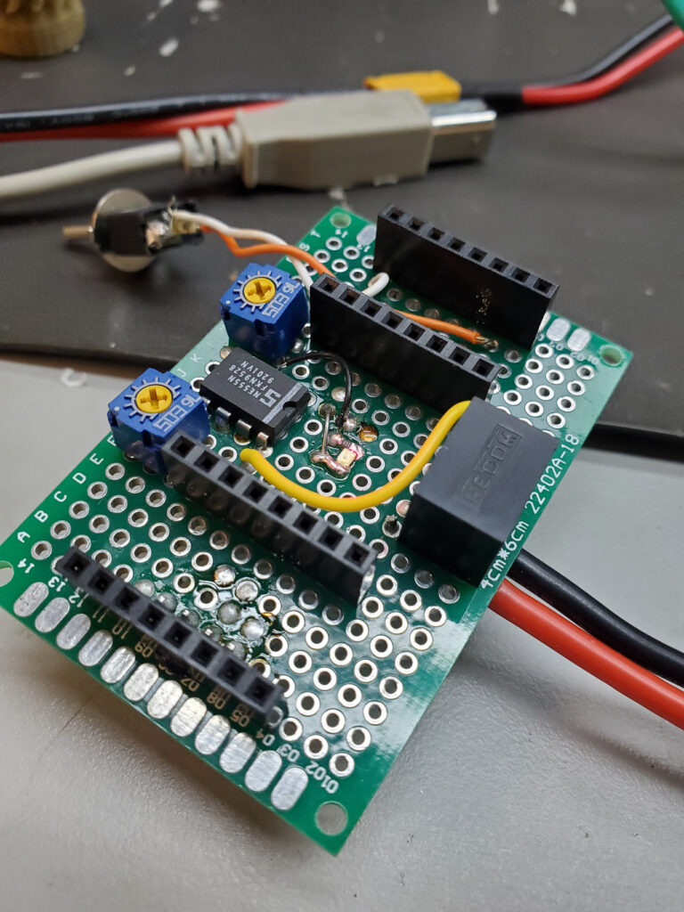
Bit of poking around with a scope verified the signal I was expecting was correct and I moved on to mounting it to the machine for test.
I knew from the beginning that I wanted to use some type of rubber roller. But wasn’t sure what I could get locally. After a bit of searching I found this round belt pulley generator on thingiverse that uses openscad. (Much respect to Follymaker for the work)
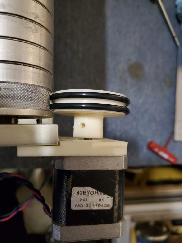
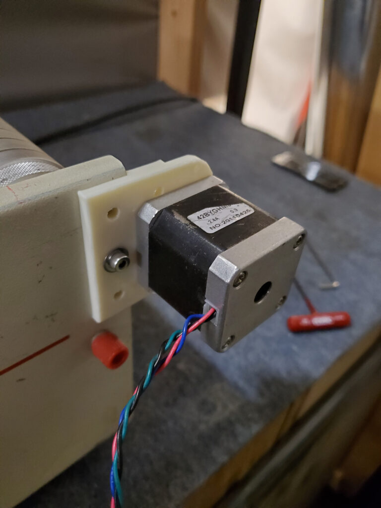
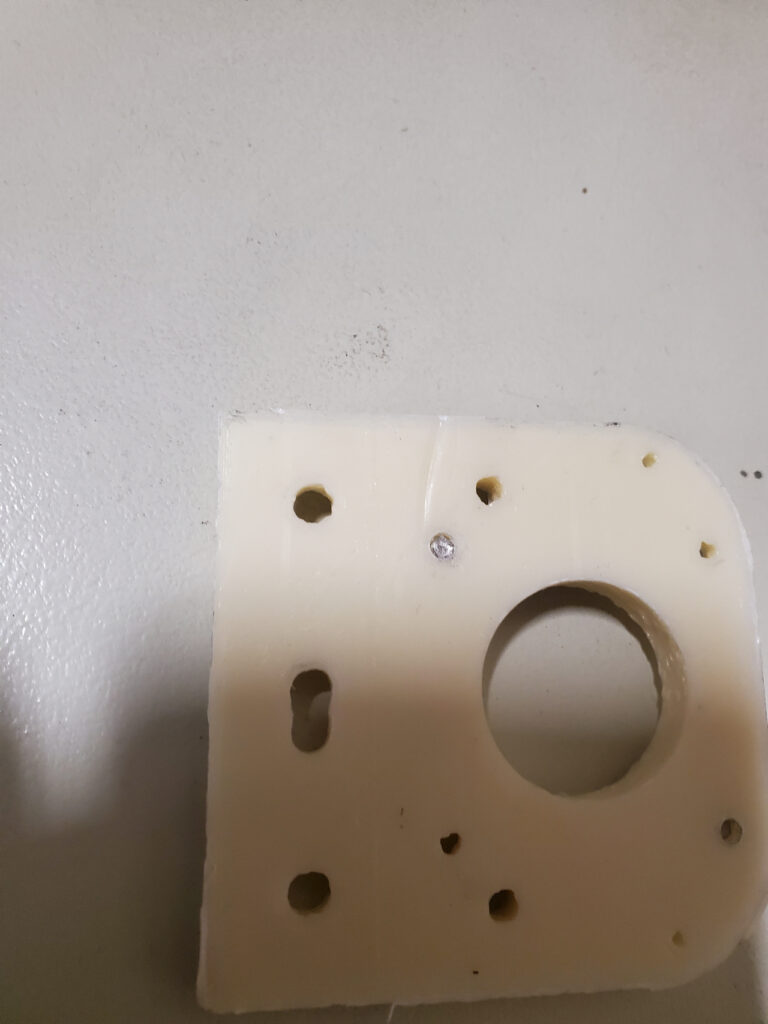
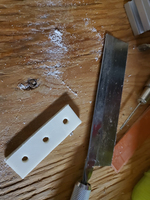
My first measurements I figured a 45mm pulley would work. And I happened to have a motor mount from a printer I built recently which worked perfectly (this almost never happens to me). I only needed to make a hole into a slot and cut part of the idler off with my hand saw.
It mounted perfectly but after some math I calculated the mm/full step would be in the area of .7mm…clearly this was not ideal since it would lead to jerky motion. I could use some .9deg/step to cut this distance in half but it might be easier to make the initial drive pulley smaller.
So after some more math I figured that I could use a 20mm pulley driving a 23mm pulley with some orings wrapped around the idler pulley to allow it to be driven as well as have grip on the drum. This got the mm/step down to ~.3mm.
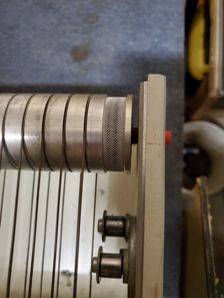
It just so happens that there was a hole perfectly in the correct spot for the idler pulley to sit and be mounted with the pulley sizes I chose. So again…this required no redesign to the mount.
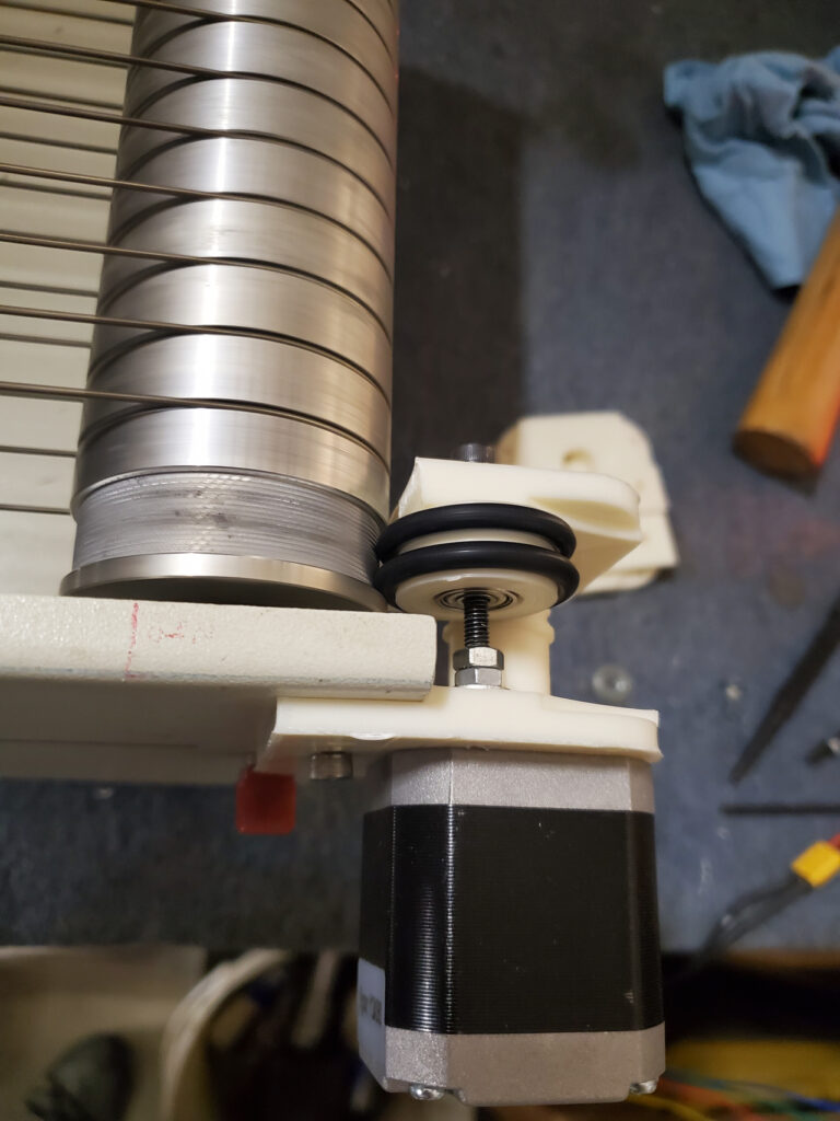
A bit of tuning and measurement of the time and I had my conveyor speed set and consistent. I even added a latching pushbutton on the enable and a toggle switch to the direction pin…so I can actually reverse direction if needed (an option it did not have by default) or stop the conveyor (an option it does have by default).
What’s the next step? Aside from putting a label on the board as a joke to future me to remind myself “This is only temporary”.
I do plan on building a small board that fits a bit better and probably will integrate the power into the machine since I can use a wide range of DC (I am pretty sure there is a 24vdc in there). My next thought though is to measure the PWM signal to the default DC gearhead. If I can get a chart of what speed the machine corresponds to which PWM it will be easy to make a board which can plug in and set it’s speed based on the speed indicated on the front panel. That is all for later though. Again, in the long term this is my backup oven.
Just thought I would give you an update into how things are going with production as well as a small glimpse into what it is like in my world.
Murphy’s powers are strong in my proximity…I have learned to cope.
When everything breaks…you need to learn to fix it all…nobody is going to do it for me.
Chris Cecil