Alright. Just to start this update will be a bit of a long one and I may need to do it in sections.
The V2 Smoothieboard progress has been slow but it overall has been very productive. After reading this you will not only get an update on the progress of the project but an overall understanding of some of the pitfalls and issues which befall anyone looking to undertake a major project with a small team. Don’t get me wrong…it is amazing what a small team can do nowadays. Just this project alone would have taken a room of draftsmen, engineers, technicians and programmers just a few decades ago. In the last decade alone the tools have become widely available to anyone with access to a computer and the internet. The availability of quality OSS is amazing let alone the fact that we have access to amazing amounts of information and writeups which make things so much easier. I hope others follow the same path as this project and do whatever they can to move their own ideas forward (even better if they give that to the world as a gift).
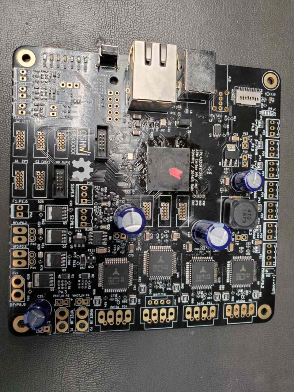
Anyways, Back on track. This story is about the V2 Smoothieboard (Prime Alpha).
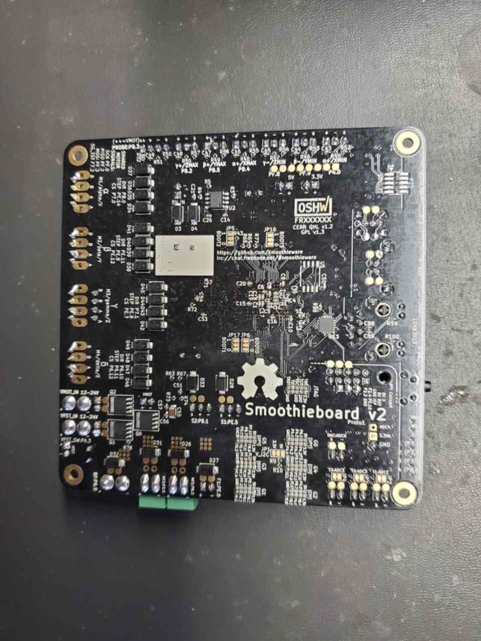
We got the first batch of prototypes quite some time ago…and at the time there was still not a full working “flashable firmware” for them. In our rush to send one to Wolfmanjm we had to do so without full hardware debugging. Once he got his board and developed a working firmware we quickly found several hardware bugs…some minor and some more major.
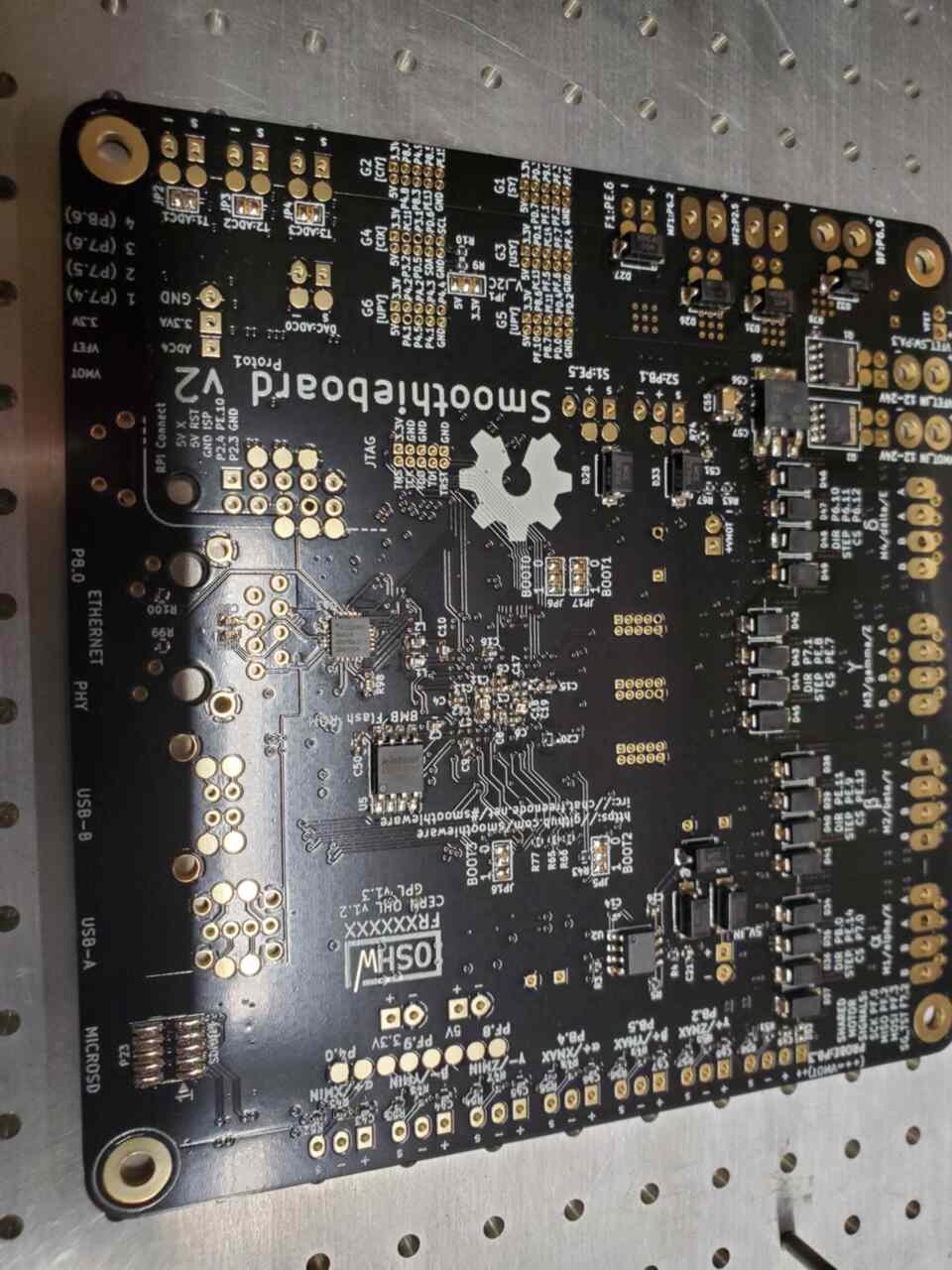
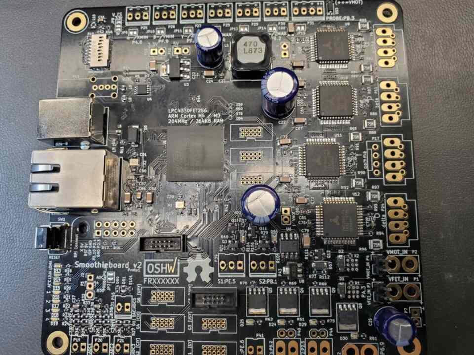
Smoothieboard V2 Prime Proto1 rework instructions:
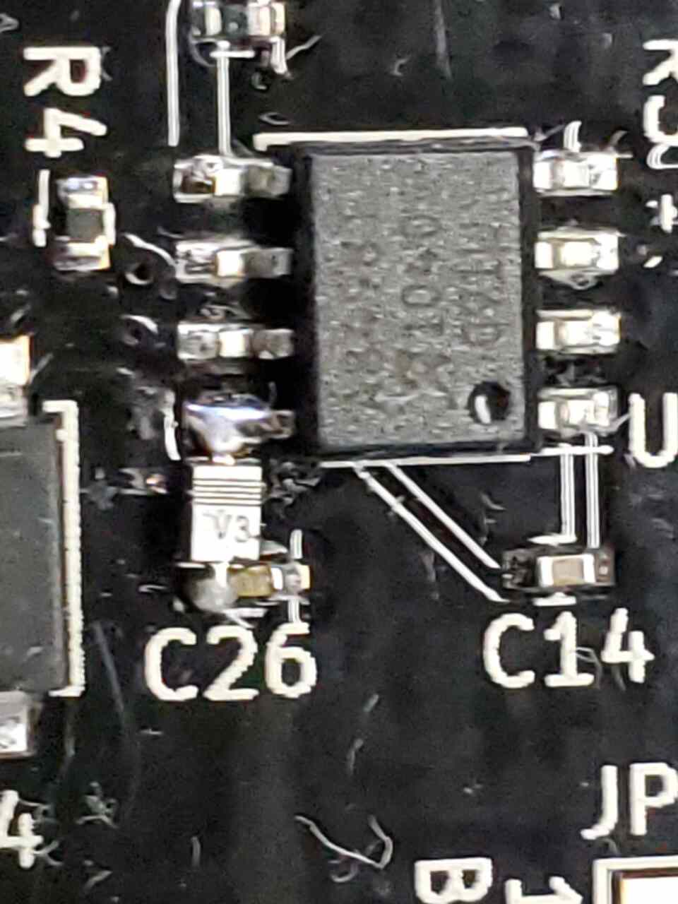
Issue 1: 5v Regulator backfeeding into the VBB line.
Cut trace between U2 Pin 8 and C26.
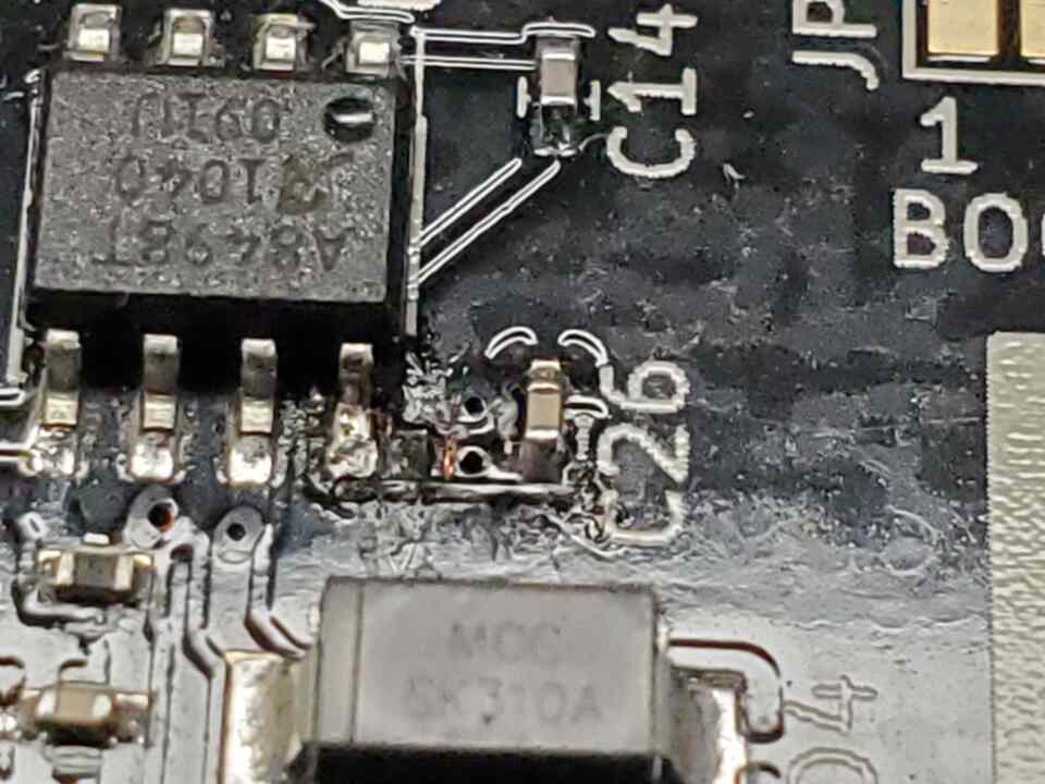
Bridge cut trace with Diode (Schottky 40v 1A SOD323. Cathode facing U2
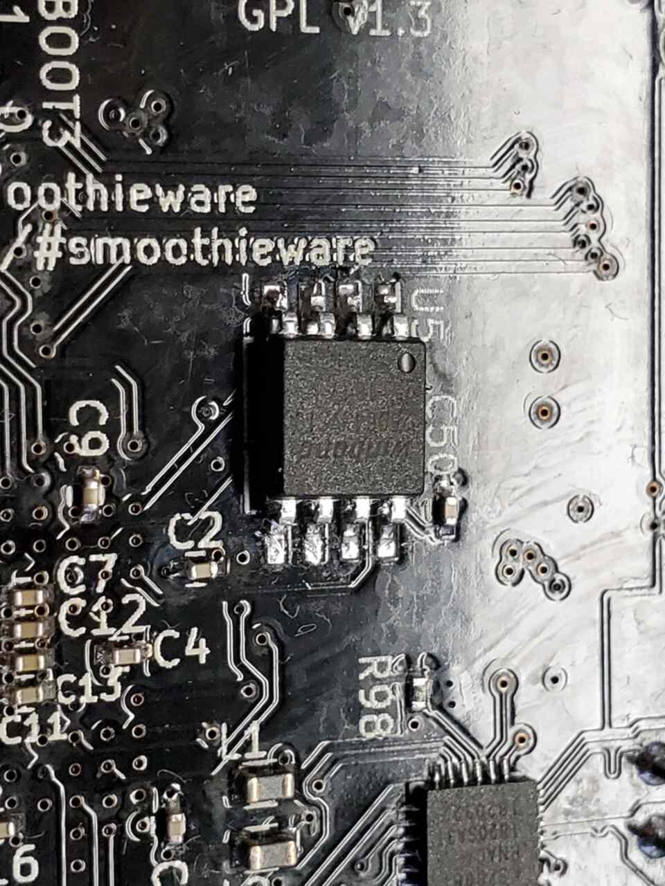
Issue 2: Flash Chip install
Install flash chip in U5 location.
Issue 3: Stepper drivers not properly setup
Bridge pins 19-21 to setup proper logic
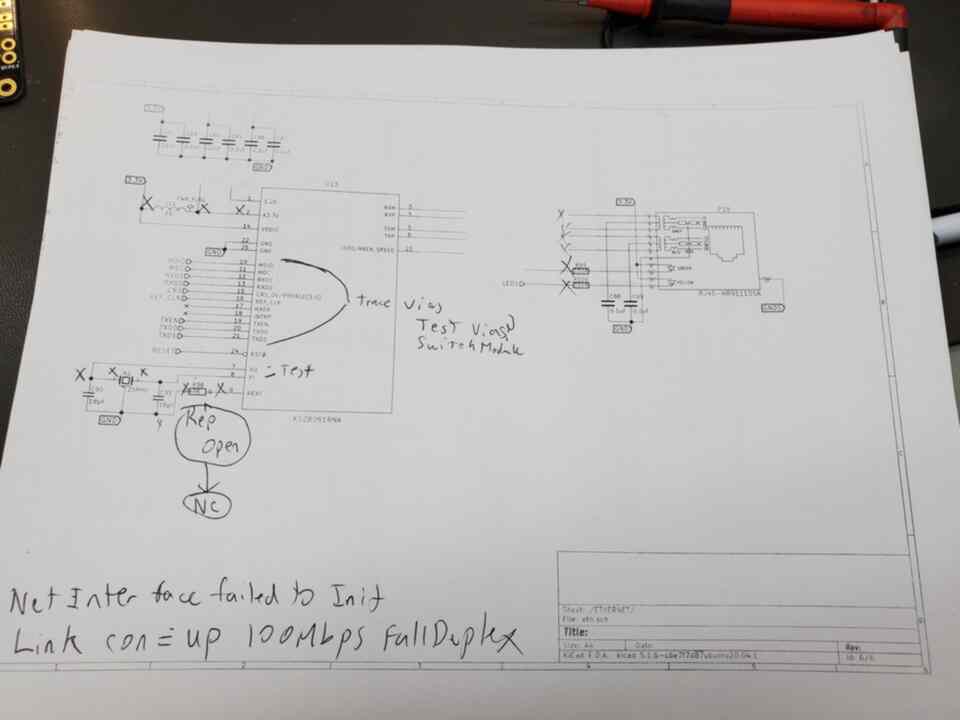
Issue 4: Ethernet toggles between half/full duplex
Tested quite a bit, determined probable need for inline resistors on data/clock.
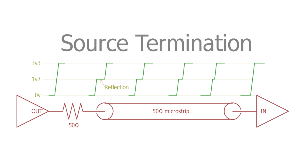
EDIT: After speaking with Triffid Hunter a bit about this he agreed it is very likely the lack of source termination in the data/clk lines as we suspected. He even had a diagram explaining the issue since it was recently something he encountered as well. What needs to be done is that inline resistors need to be added to the traces which match the trace impedence, and they need to be placed as close to the source as possible.
Issue 5: Protection MOSFET does not shut off.
Fixed on second prototype Tested 9/2020
Issue6: SSR outputs Nerfed
Fixed on second prototype Tested 9/2020
Issue 7: Incorrect thermistor readings when VMOT is off
5v line not connected to thermistors.
Connect 5v to AOV signal, Schottky diode with cathode to pin1 of D12 and anode to 5v
Issue 8: 12vreg inverted.
Swap pin 1 for 3
Issue 9: Vmot/Vfet crosstalk
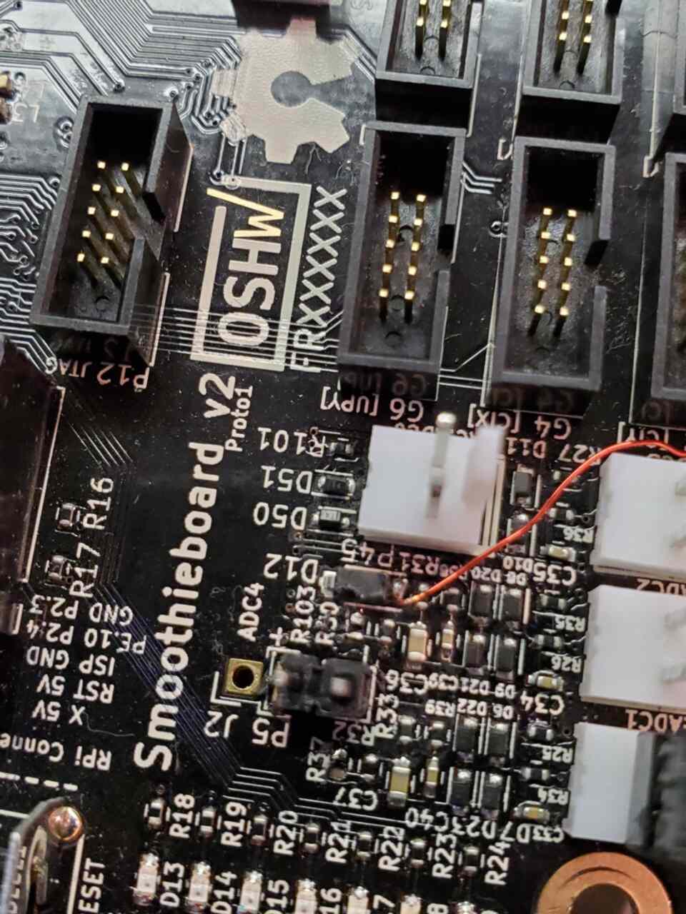
Remove R37/R103
Fixed on prototype 2
The most major being that the ethernet would connect but would toggle between full and half duplex. This issue was a bit annoying since it seemed to be worse for WJM than it was for me. In order to require triggering of the issue I needed to be printing and have a travel move. WJM could trigger it just by hooking up the power. We determined it was noise related and Logxen added it to the board revisions to be closer to a “known working” design.
That being said. I have been using one of these protos (with only about half of the “fixes”) since last August in my printer and it prints very solid. The TMC drivers did seem to make my leadscerew based printer quieter and smoother. During this time I was also helping test Smoopi host with WJM in order to help encounter issues and pester him. Trying to ask all the dumb questions and writing them down so you don’t need to….but that is for another writeup.
So fast forward…Kickstarter is done and board redesign is in progress. It takes a bit of time to get all that organized and PCBs designed…BOM rewritten and such. Then during the time where parts are being ordered and everything is starting to move forward…the pandemic hits. There was obvious delays in some areas but at the same time during the lockdown and uncertainty some of us took the time to work on other areas of the project…documentation, test, etc.
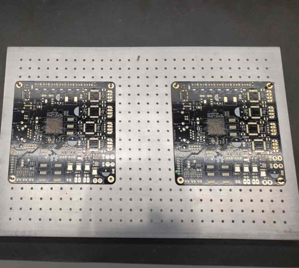
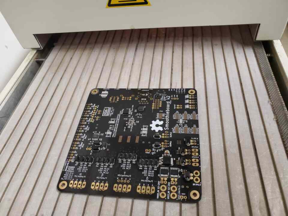
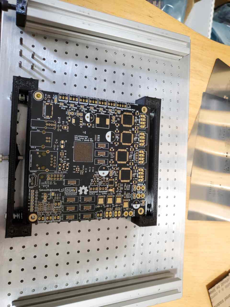
So finally, I had in my possession the bare PCBs and all the parts to do the assembly.
Go back 1.5 years…I moved out of the shop I was in at the time and put the majority of the production equipment in storage. At the time there was some issues with the oven (talk about that later) and a slight vacuum issue with the PnP (head 1) but where it was located I could get it setup and use the small oven after doing some minor rewiring of the building and such…and adding air.
So. I get the air installed and fire up the PnP…a Manncorp 384v (dual head with paste extruder) which is adequate for this build. After I do the work to import the CAD…test the motion and such I realize 2 things.
1) The air leak now is bad enough to the point where the machine will no longer autosense board height…a bad sign. (this is something I expected to get worse though as I suspect some air lines are leaking, general maint is required and we bought this used).
2) We don’t yet have the platform to have short component strips mounted in a plate. I am going to build one but I didn’t have time for all of that.
Since we were building 3 boards I figured I might as well do it all by hand…I mean how hard can it be…0402 and BGA…sounds like a cakewalk. 8 layer double sided PCB just makes this all easier…right?
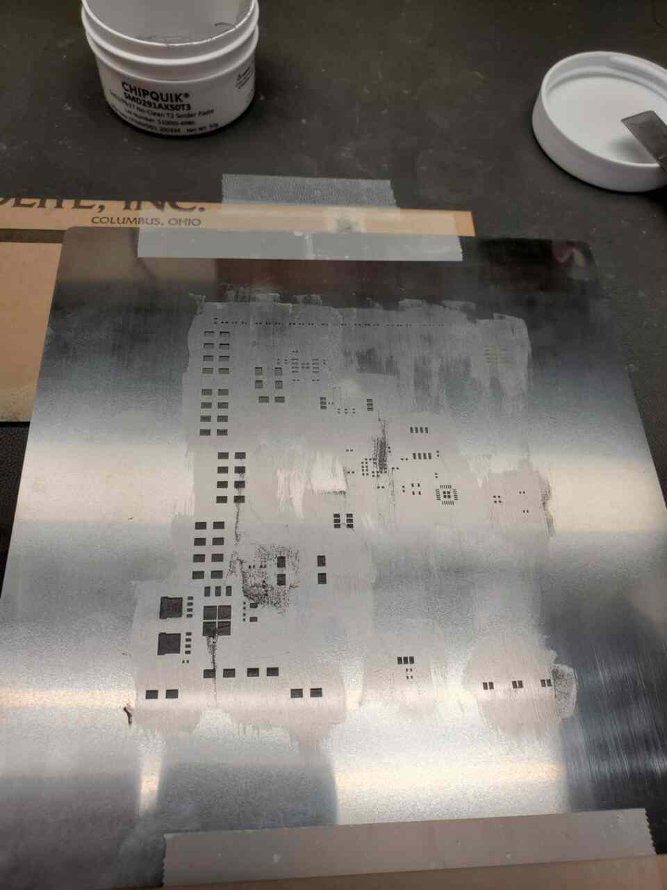
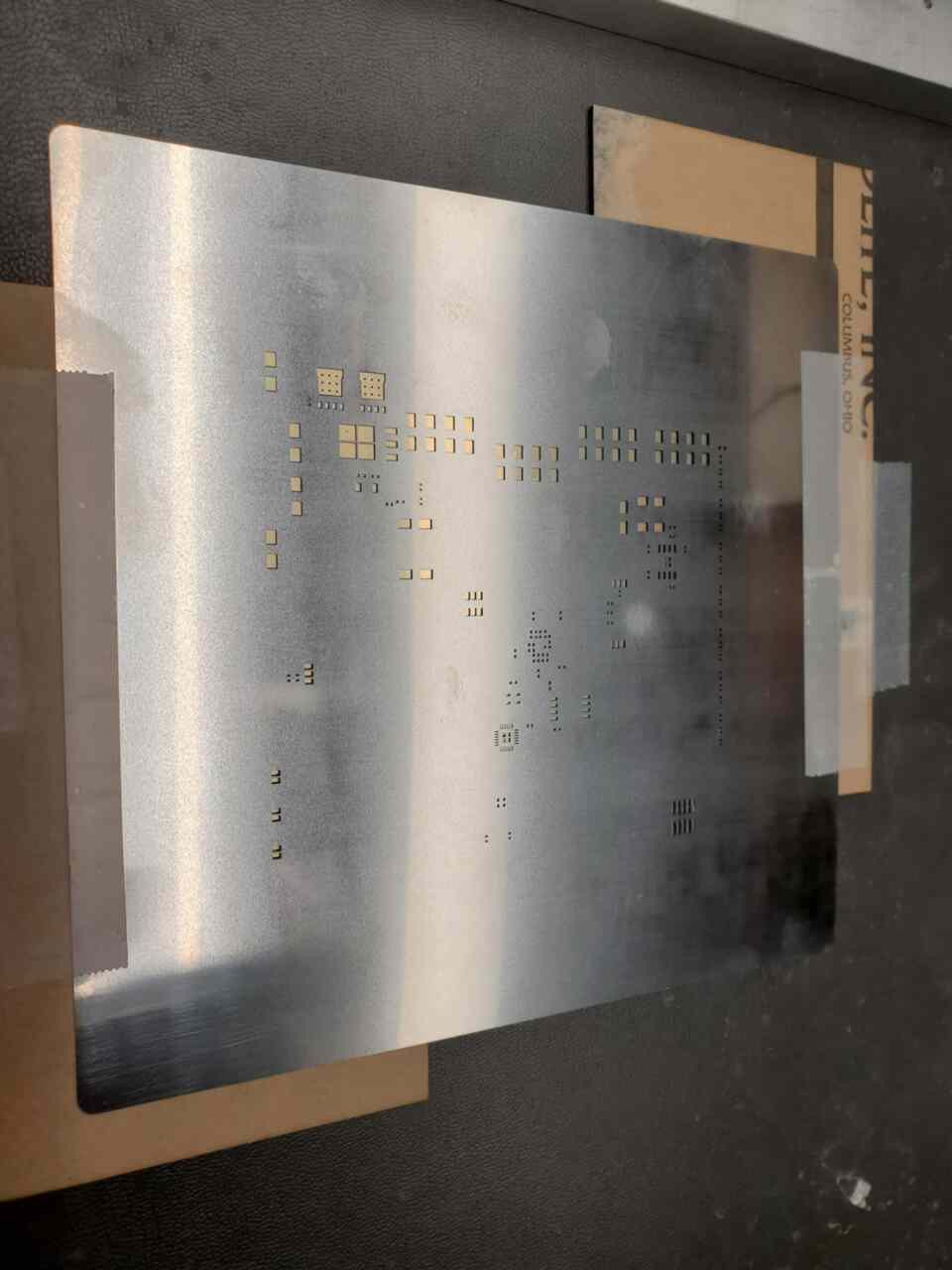
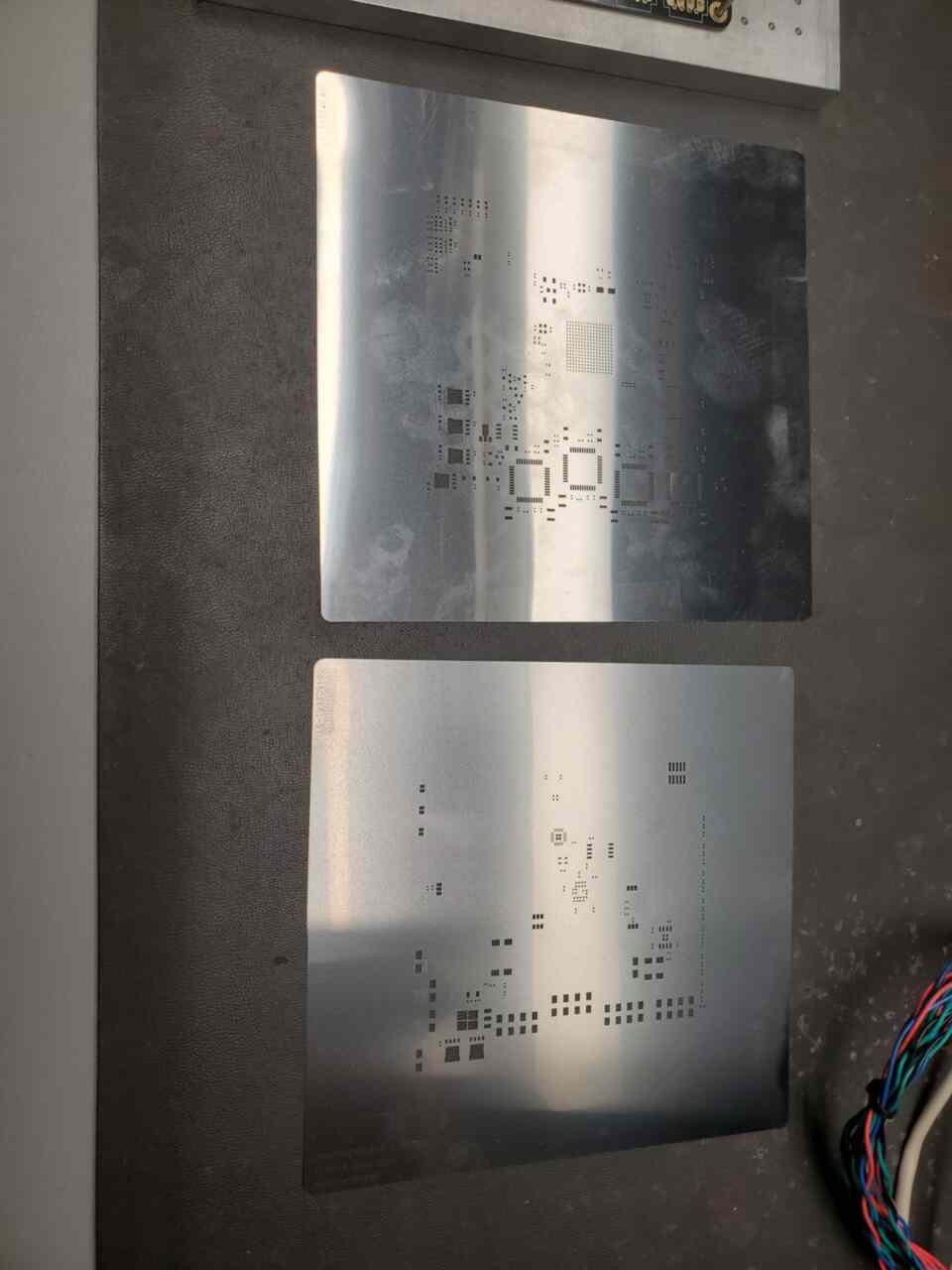
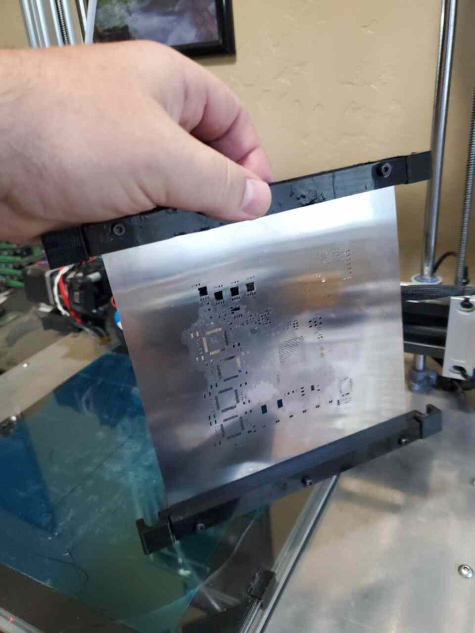
So for the first 2 boards I did the oldschool method of taping down the stencil and board holder…but it didn’t work “great” so there was some bad spots….and since this board/stencil lacked the “Stencil8” pattern we typically use I was unable to use my proper jig.
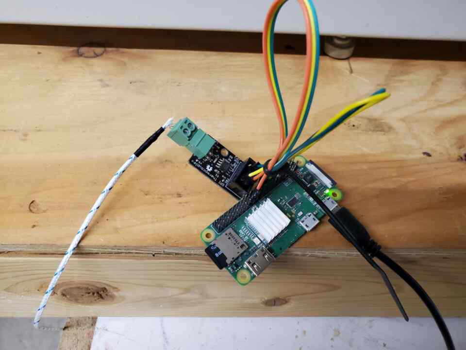
After placing components by hand in my home lab…I drove the 1 mile up to the storage/shop where I had the oven installed and ready to go (or so I thought). The few days before this I spent some time building a thermocouple datalogger based on a board that Uberclock produced which allowed reading a TC via SPI.
So I fire up the oven and I start running it. The conveyor had a known reliability issue which we had encountered in the past (small oven…big oven required 3phase which we didn’t have at the storage).
After testing a bit I realized a few things. One was that the conveyor was too unreliable to run these boards and the second…was the dread of realizing someone else had been inside the small oven before me.
They had apparently replaced the 3rd bed heating element. During the replacement they routed the wires in the wrong location causing them to drag on the conveyor wires…seriously…I couldn’t make this up. That coupled with the gearhead DC motor being kinda noisy and the belt looking a touch ragged I decided this warranted a full rebuild.
10 working hours later…I was ready to fire up the oven. I rerouted all the wires, rebuild the gearhead on the DC motor which was loose, flipped the belt over (might not be the best choice) and also did a full planned redesign on the conveyor system for when this one fails again. (seriously manncorp…this little oven could have been so much better with just a little more work.
The machine is very much designed to require a full teardown in order to do some simple maintenance things which will need to be done…if nothing else it gave me ideas on things to avoid in my machines 🙂 Again though…that is for another post entirely…
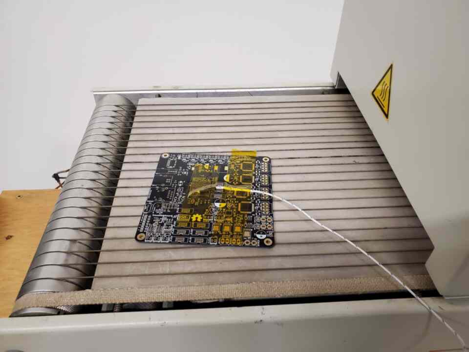
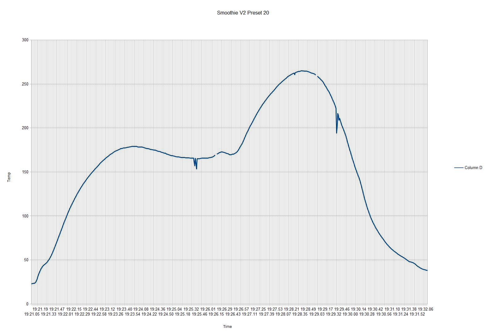
So I started test with the thermocouple datalogger taped to a bare PCB. I ran the board a few times starting with the “suggested” profile included in the oven manual. It got me close but was still way off. I took my datalogged information and fed it into an Openoffice sheet and then plotted the infornation to give me a picture of the reflow profile which was going to be created on the surface of the board (yeah…I know I am supposed to do this with a ton of probes and components on the board…but this is cheaper and that is a project for later).
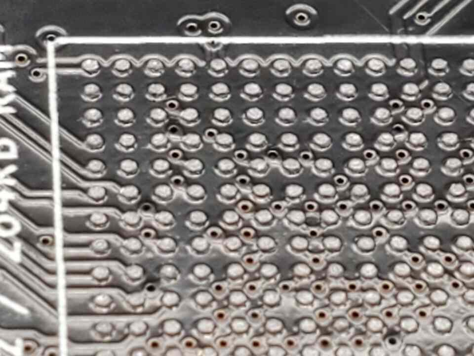
So after the first reflow things look pretty good except for the areas which the solder paste was not perfect. After taking note of that defect I started thinking of a solution while beginning rework.
Rework on these boards is not exactly easy. They are heavy, 8 layer PCBs using very small components. But I like the challenge 🙂
So after preheating and doing the rework under the microscope it was time to figure out how to paste, assemble and reflow the top side of the board without having issues.
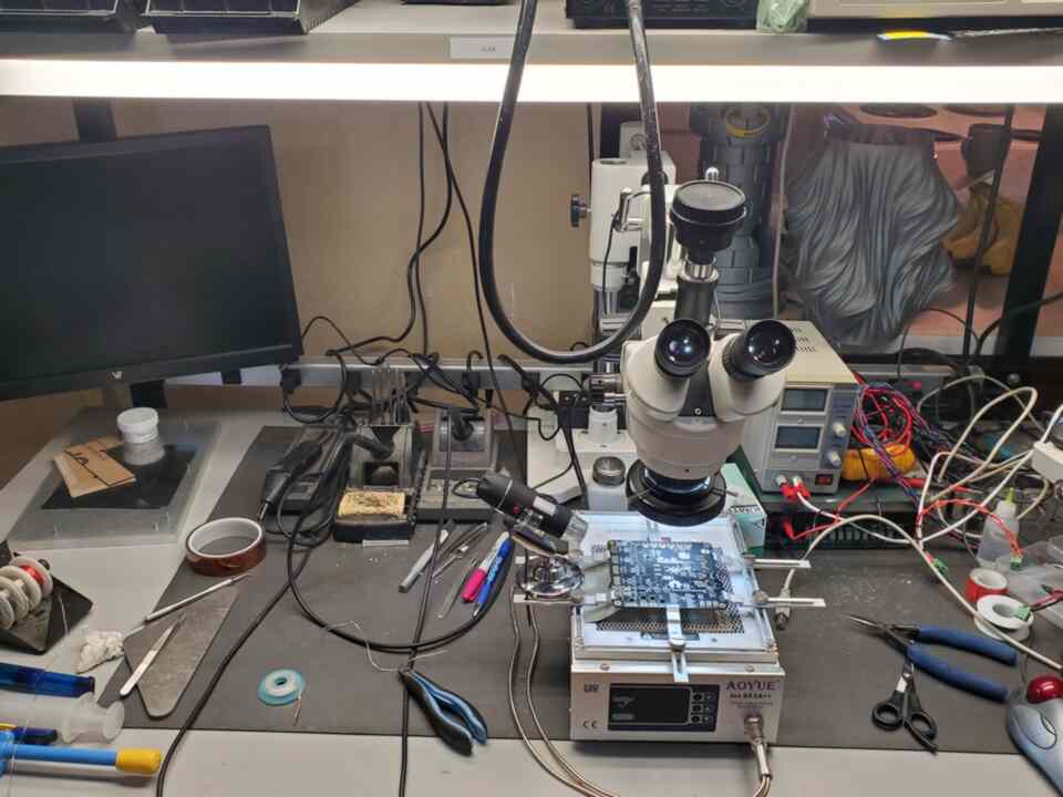
First for the paste. I did not want to repeat the issues of the back side of the board with the top side…especially with the BGA…but the “pro” stencil jig is inoperable and requires a custom stencil…the hobbyist “stencil8” jig which I typically use I couldn’t due to lack of locating pinholes.
So I was off to Fusion360 and creating using the main tool at my disposal…my 3d printer.
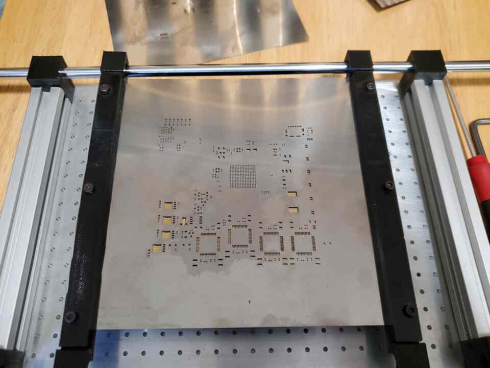
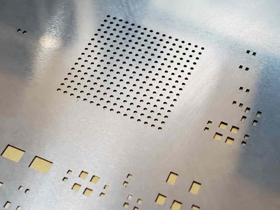
After spending some time designing and thinking…as well as looking at several other homebrew designs for a similar thing I came up with a jig which was able to be aligned and would hold the stencil in exactly the place I needed in order to get the BGA paste aligned.
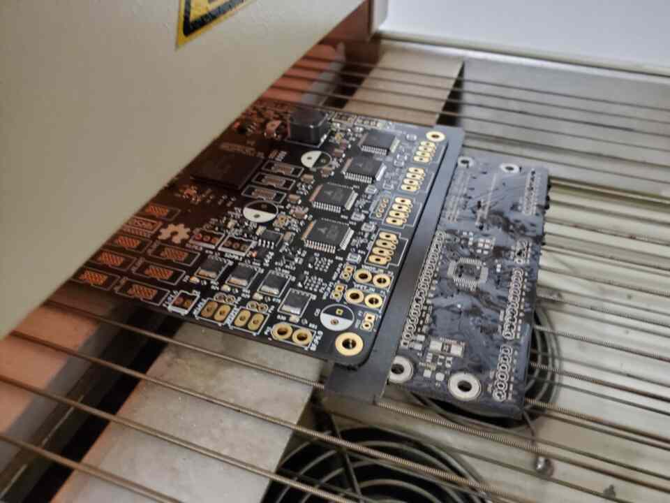
Then I hand placed all the components again and attempted to get the boards up to the shop/storage to flow them. During that time one of the BGAs got bumped and was slightly misaligned…I attempted to fix it before reflow but without a scope and such I failed. So during reflow that one moved a bit…in post soldering I attempted to reflow/realign it…but anyone who has done BGA work probably knows that was a mission with a low likelihood of success.
So now after the rework and installing connectors I was able to flash the FW to the first board and begin testing. The board appeared to work as the first one did…but now the ethernet would not boot at all. So after discussing things with everyone and attempting to work on this remotely we came to a point where we had to pause and regroup to decide where the issue was. It can at times become very difficult to relay to the team exactly what the issue is…”old board works…new board doesn’t…old board seems to function better than before…but not everyone can repeat results”.
Found a new shop. Began moving everything to the new location while maintaining ability to work/test.
After a couple attempts to get this resolved over IRC/Slack we came to the decision that Logxen was going to need to come up with all the docs and sit here with me at the new shop and do whatever it takes to find every issue we can. This took a couple more weeks to get arranged and planned. During this time I got the new shop mostly setup while doing a bunch of rework to some OEM V1.1 smoothieboards
So Logxen came up a couple weeks later and we spent the entire time testing and reflashing…pacing back and forth mumbling to ourselves trying to figure out why the ethernet doesn’t work…getting distracted by boxes full of unfinished side projects and possible designs we have all the parts for but need to put together.
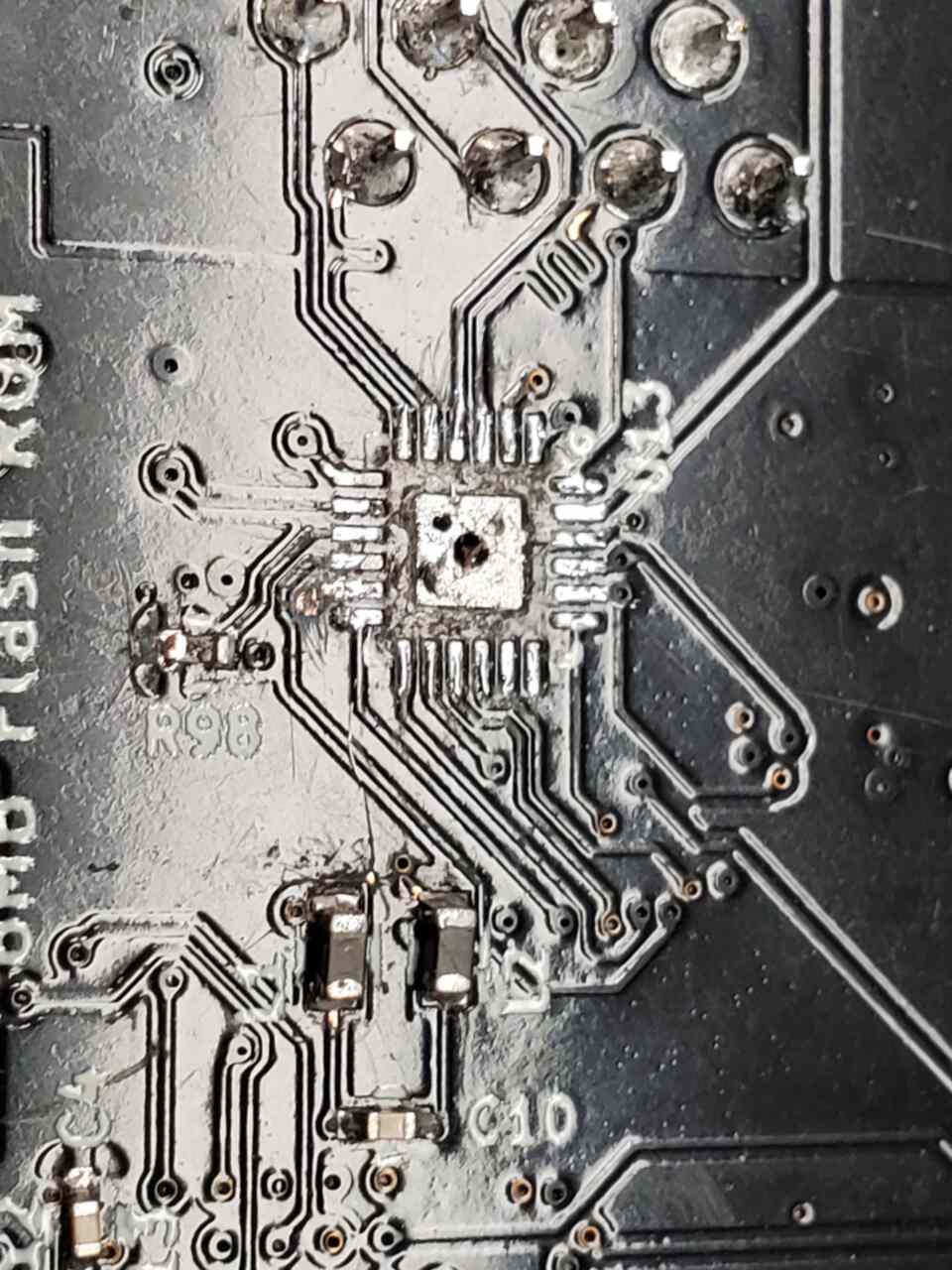
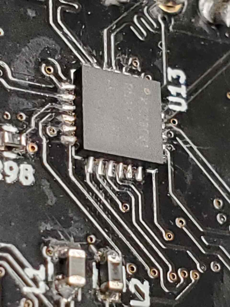
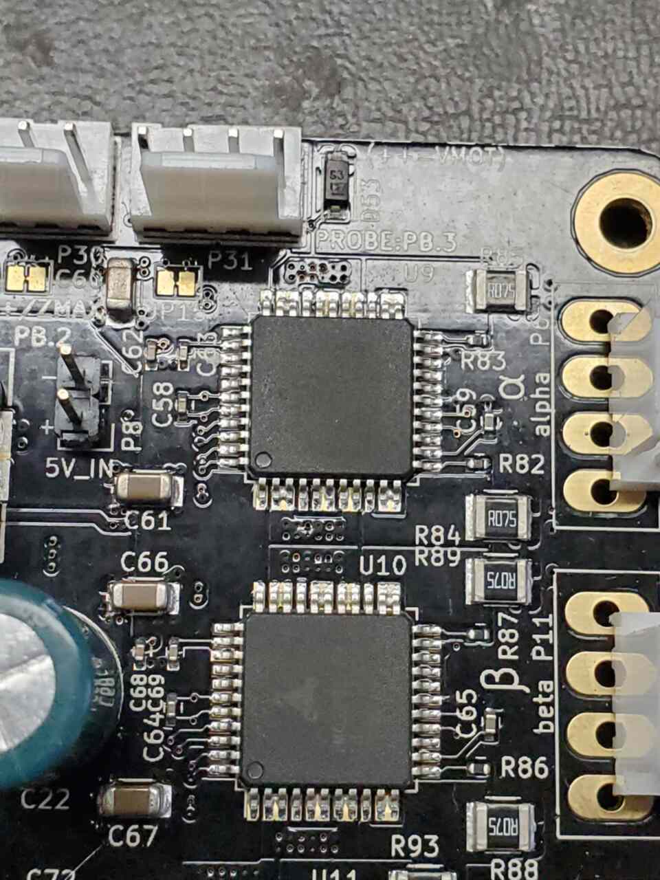
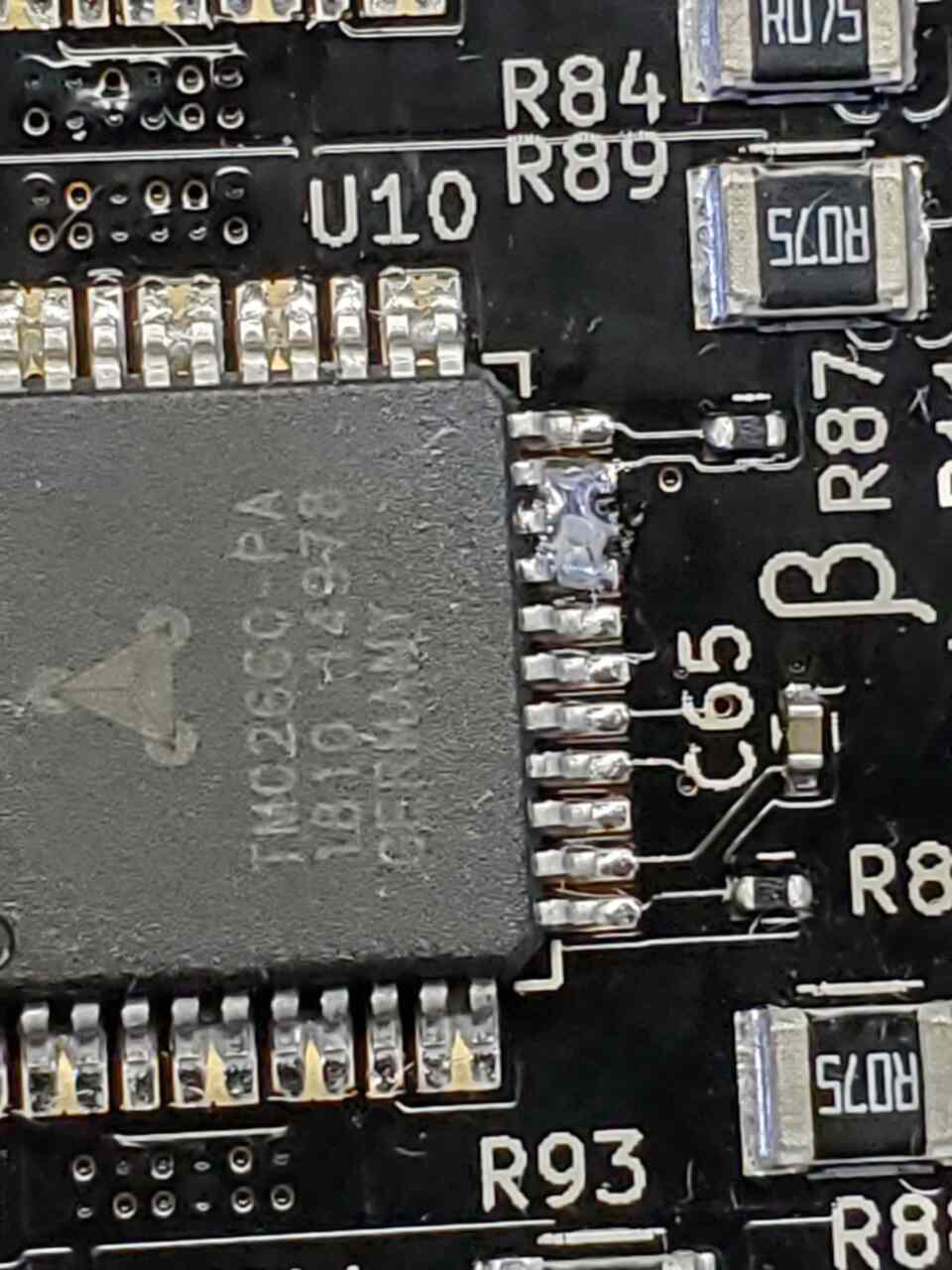
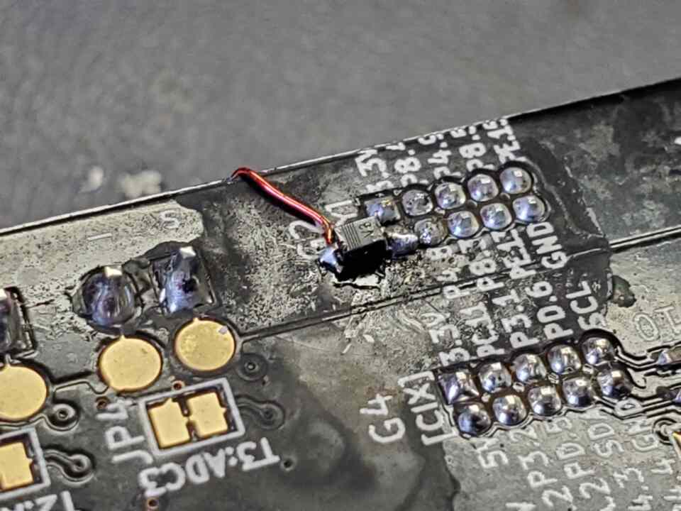
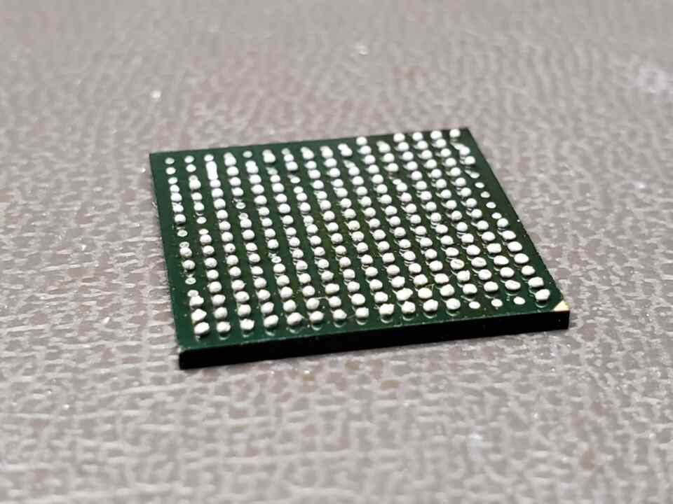
We got a lot done surprisingly though given our limited attention spans…but not having internet at the shop may have helped there. All of the fixes were working, all of the fixes which were supposed to be done but got missed were noted. Finally, after much time looking at the board under increasing magnification levels I found a solder bridge right at the body of the PHY…”ah…found it” I thought…but I was only partially correct. The bridge was fixed but we were not getting the signals that were expected. We realized the Data and CLK lines were tied together…and given the timeframe that we had been attempting to test it there could very well be a bad pin on the MCU. So we pulled the PHY and tested directly at the pin and indeed…no CLK signal…so we were off to verify closer to the MCU. As this is a pin (by chance) which was on the outside corner of the BGA I could inspect under the chip and see that it had connection for sure…so we decided that we needed to replace that MCU and order some extras (as well as a reballing kit for the other MCU which was misaligned). During the review of the design we realized the spec of the PHY suggested that there be 330ohm resistors in these 2 lines from the MCU. The example circuit we used did not have these but they also do not have motors onboard. So not only would the resistors prevent the pins from burning out in the future due to shorts..but they are supposed to help with “reflections” on the signal/clk lines…which could very well be the original noise issue which we encountered causing the Full/Half duplex toggling on the first prototype. (Any community input on this matter would be appreciated, we are not “experts” in the field of ethernet and it’s common fault modes).
Today as I write this I just received in the mail the replacement MCU as well as a couple other parts needed to revise and test the second version of the prototype. I still need to verify the ethernet works and then install the remaining connectors in order to install into a machine for a full test. We have some very cool features related to the ethernet (which when it works is very fast BTW) and this issue is our primary blocker before moving into production. The other small issues have been largely resolved and should be fixed on the next PCB version. So once this board is tested (planning on this week) we should be ready to get another proto PCB sent to me so I can assemble and verify that it is ready. Things will go much faster this round since all the reflow profiles are figured out (and depending on timeframe I may be able to use the big oven, which can do both sides of the board at the same time).
The firmware is evolving and already very capable. WJM and I have both used it on printers and he has also used it on a laser. I believe it is ready to use on mills as well but there has been limited testing as of yet. [edit: WJM confirmed he is running it on a mill as well 🙂 ] Looking forward to the next revision so we can get production started.
Chris Cecil,
Robosprout