Smoothieboard V2 Prime final Revision features.
So as we finalized some of the features on the V2 prime it is a good time to do a writeup of what to expect. Please be aware I may be slightly off on some specs but I believe this information to be accurate.
MCU-
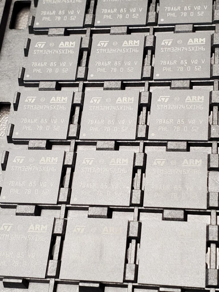
As you probably know we started with the LPC4330 but due to parts shortages we were forced (to the glee of some of the devs) to change to the STM32H745. This MCU should be a bit better overall and Wolfmanjm seems to be happier with this choice than he was with the LPC.
We chose the 265 pin BGA version of this chip and procured enough supply early on to fulfill the entire kickstarter plus some sales. Since we purchased these parts there have been no new supply of them on the open market. Although, I have seen up to $500/MCU on the grey market. From this point forward even when supply resumes they will cost ~$25/MCU based on statements from suppliers.
Here is the link to the datasheet {https://www.st.com/en/microcontrollers-microprocessors/stm32h745-755.html}
Stepper drivers-
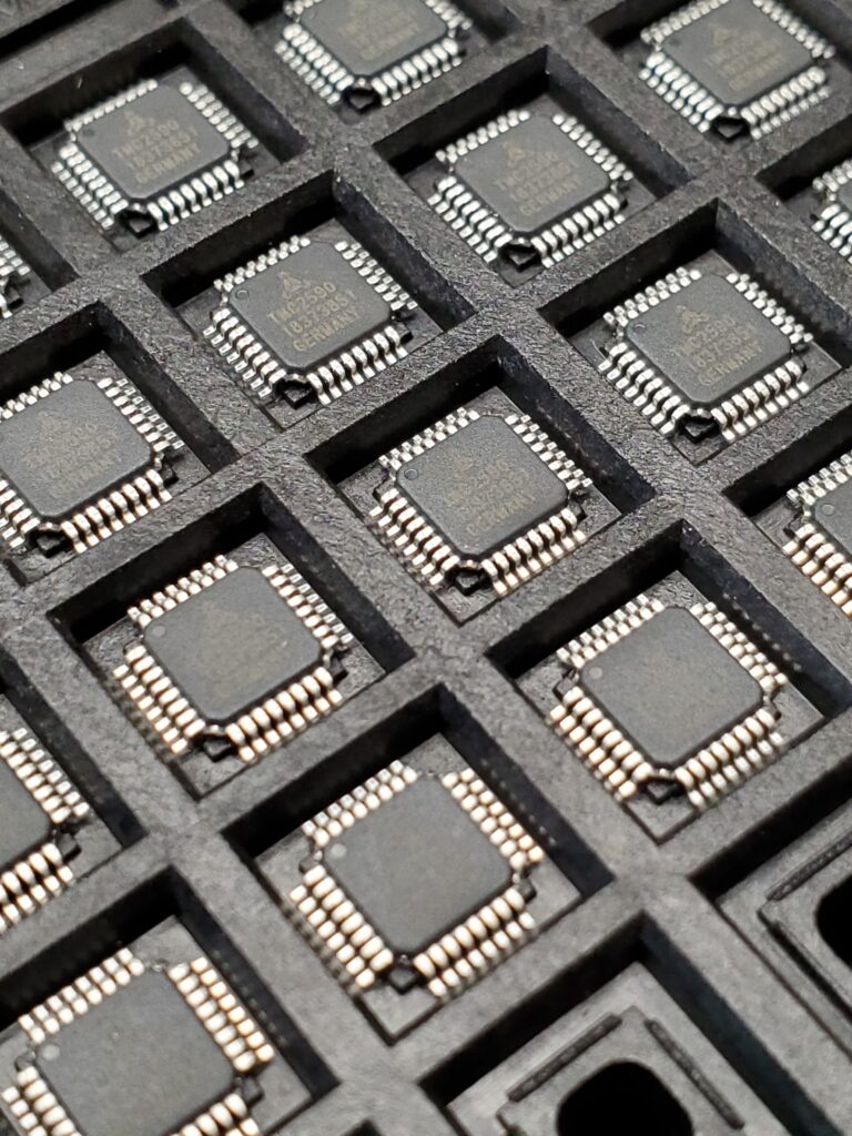
Originally we were planning to use the TMC2260 which we tested on the early revisions of the board. The chip shortage forced us to choose to use the TMC2590 initially, then there was huge delays on the shipment and backorder of our parts. So we made yet another design which uses the TMC2660 again…since it had come back in stock.
Now our plan is to release both versions. The TMC2660 version is better tuned for the lower current motors 1.2-2.2A and the TMC2590 version is tuned for higher currents 2.5-4.6A . These ranges are set by the sense resistors…which potentially can be varied to change the ranges.
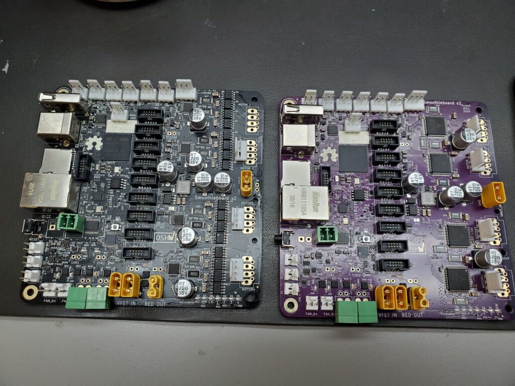
Other than the stepper drivers there is no significant difference between variants of the board and should be drop in compatible for all other features other than motor current…although, there is some overlap on that too.
So far these function very well on both boards. I have been running a leadscrew based printer as well as a router table from different board variants. I believe Wolfmanjm has been running deltas and lasers as well as mills and standard printers.
Motor power is supplied by it’s own XT30 connector which also supplies power to the onboard 5v regulator
Output FETs and connectors-
There is 4 lower current FETs which are intended to be used with things such as hotends and fans. They are all connected to a common +VFET point which is controlled by a highside PFET for added watchdog safety in case of lowside FET failure.
The bed shares the same FET type but there is 2 paralleled for higher current. The bed FET is independent of the highside PFET and is not controlled by it.
There are 2x XT30 connectors on the VFET input which should allow for up to 30a of continuous flow (15a/connector continuous). This was preferable to having a larger XT60 connector which has a much larger vertical footprint. The second connector is usually not needed but in the case of 12v systems it would be very easy to overload the 15a connector if a large heated bed was used (or the entirety of a 400w@12v psu).
Endstops-
No significant change here from the V1 endstop layout with the exception of an added buffer and ESD protection for all inputs. Still 6 inputs with XYZ min/max labels
Probe-
This was an area with a bit of added work. We put in a comparator on the probe input as well as other ESD and buffering protections. This will allow use of a variety of probes. Everything from a simple switch up to active inputs which are up to 24v. For higher voltages (i.e. 40v inductive probes) we are planning a daughterboard expansion which plugs into the probe input for protection of higher voltages which will use the exact same parts but with higher range tuning.
ADC inputs-
We have 3 buffered and ESD protected ADC inputs which can be used for thermistors. This should have a stability improvement over V1 (in theory) and allow for more stable readings of temperature.
There is also an onboard thermistor for sensing board temperature.
6 unbuffered ADC inputs reside on 2 gadgeteer headers and there is a planned daugterboard which will plug in and allow identical expansion of the 3 onboard ADC inputs (or other options which require hardware on the inputs).
-LED indicators
We have indicators for the Vmot, Vfet, 3.3v and 4 status leds for the MCU debugging. There are also LED indicators on all MOSFET outputs.
A single LED also indicates MSD function when selected.
-5v input options
There is an onboard 3a@5vregulator which is powered by Vmot which is the preferred method of powering the board and all peripherals (on my test setup I am powering a raspi and 7” touchscreen from the onboard 5Vreg).
Second to that is a USB input which is current limited and has physical jumpers which can be cut to hardware disable the USB 5v input. This allows for devices like raspberry pis to not attempt to power the board.
After that there is a 5v input header which allows for a direct input to the 5v system.
All 3 inputs are protected with ideal diodes which allows for backflow prevention between connected 5v sources but also has very little drop unlike what you would expect with standard diodes.
MSD pushbutton-
In the past there was often an issue when the MSD was mounted to a host computer and it would cause communication issues while running a job. This has been solved by adding a pushbutton to the board. If you press this button (or send the command) it will go into MSD mode and mount the board as a storage device until it is ejected by the host.
Ethernet-
Function of the ethernet is much better on this version. Features such as autoupdate have also been added. {get wolfmanjm to inform on functions}
SD function-
We now have SD running over SDIO instead of SPI…this will allow for significantly higher transfer speeds over the V1 board. This was a big issue with most users…and at times myself.
Yet unused stuff-
Currently, we have some stuff onboard which is hooked up but has no function in firmware.
USB host- This currently has no function but is ready and capable for the code to match…make it do something useful.
M4 core- Right now…the firmware resides in the M7 core. The M4 core is completely unused and disabled.
RTC battery- Footprint and connections are there to hookup a RTC to the board. As far as I know there is no plan to use this…but it is there.
Gadgeteers- There are 9 headers with 7 spare pins on each. Some have various functions such as SPI, I2C, ADC and GPIO but this allows for easy connection of expansion and breakout boards.
Cool features so far on V2.
-Autoupdate via ethernet
Just send “update” command and the board will automatically check, verify, download and update the firmware if needed.
-Parallel motors on the same axis in software
Recently added was the ability to parallel 2 motors in config and have them act as a single axis. This feature has long been asked for my multiple users but was not easy on V1 due to limitations.
Along with this feature has been the ability to probe across the axis to independently align 2 motors (such as on a Y axis on a router table with 2 motors/actuators). You can attach a probe to the X axis which probes Y length and physically compensate based on errors in alignment during homing.
MSD function-
This really does make it nice to just make the board appear as a device to copy files to it. Although, there are multiple methods of transferring files to the onboard SD card. The board flashes an led when in this mode and remains in the mounted state until ejected at which time it resets the board, reloads config and if applicable reflashes firmware.
So where does this all leave us?
We are finally ready to begin fulfillment. So far all the issues that were known are solved. I am beginning production this week and I will likely be ready to begin shipping before we are ready with the final information update. Arthur will update you with instructions in the next coming days on how to handle this. We are just now setting up to finish this and some logistics but keep watch for this information so we can be sure to get all the necessary information for fulfillment.
This has been a long journey…even before the long journey. Thank you to all our backers for being patient. Thank you to all the devs who made this happen regardless of obstacles and annoyances.
I am looking forward to seeing what everyone makes with the boards…as well as future features and developments.
Chris Cecil,
Robosprout